Flow Controls 19 Series
- Low profile, high capacity & right angle series available
- Available with NPT & BSPP port threads
- Low profile series includes slot & knob adjustment options
- High capacity series includes inline & offset orientation options
- Right angle series includes slot & knob adjustment options
loading...
loading...
Product Overview
The ROSS Controls 19 Series Flow Control Valves are a complete family of pneumatic flow control devices designed to regulate cylinder speed with high precision across the full range of industrial automation requirements. The 19 Series encompasses three distinct product families: low-profile valves for space-constrained installations, high-capacity valves for large-bore cylinder and high-flow applications, and low-profile high-capacity valves that combine compact dimensions with enhanced flow performance. A complementary right-angle series (11 Series) rounds out the offering for direct cylinder-port mounting configurations.
Flow control valves provide unrestricted flow in the supply direction and a precisely adjustable, restricted flow in the exhaust direction. This meter-out control approach enables smooth, predictable cylinder motion throughout the stroke. Selecting valves with sufficient full-flow capacity is critical: the flow control valve must not become the limiting restriction in the circuit, as undersized selections produce jerky motion and unpredictable cycle times.
All 19 Series valves use poppet construction, a design that provides self-cleaning action through high-velocity air flow across the poppet seat. The poppet geometry eliminates the bypass leakage and wear mechanisms inherent in needle-and-seat designs, and the wear-compensating poppet automatically adjusts as seals wear over time, maintaining consistent performance through millions of cycles.
With port sizes spanning 1/8 in. through 2-1/2 in. in both NPT and BSPP (G) thread formats, and flow coefficients ranging from Cv 0.5 on the smallest low-profile models to Cv 50 on the largest high-capacity models, the 19 Series covers the full breadth of pneumatic cylinder control applications from compact pick-and-place to large press and material handling systems.
Key Engineering Features
- Three Distinct Profile Families - Low-profile, high-capacity, low-profile high-capacity, and right-angle (11 Series) configurations address space-constrained installations, high-flow demands, combined compact-high-flow requirements, and direct cylinder-port mounting in a single cohesive product line.
- Poppet Construction with Self-Cleaning Action - High-velocity air flow across the poppet seat continuously cleans the sealing surfaces, providing strong dirt tolerance and reducing unplanned downtime in contaminated compressed air environments.
- Wear-Compensating Poppet Design - The poppet automatically adjusts stroke length as seals wear throughout service life, maintaining consistent flow performance and response without periodic recalibration or replacement.
- Adjustable Flow from Near-Zero to Full Open - All models provide continuous adjustment across the full flow range from near-zero to maximum Cv, enabling precise cylinder speed tuning for both extension and retraction strokes.
- Slot and Knob Adjustment Options - Slot-adjustment models use a standard flat-blade screwdriver for locked-down, tamper-resistant settings. Knob-adjustment models allow hand-operated tuning during setup and commissioning without tools.
- NPT and BSPP Thread Availability - All models are available with NPT threads for North American applications and with BSPP (G) threads for international equipment compatibility, simplifying global machine standardization.
- High-Capacity Inline and Offset Orientations - The high-capacity series offers both inline (port 1 and port 2 on the same axis) and offset (ports on parallel offset axes) body orientations to accommodate piping routing constraints in tight panel assemblies.
- 360-Degree Swivel Inlet on Right-Angle Models - The right-angle (11 Series) valve inlet port swivels 360 degrees, allowing optimal tubing routing regardless of cylinder orientation and eliminating the need for additional elbows or adapters.
- Visible Brass Stem Position Indicator - Low-profile high-capacity models incorporate a visible brass needle stem that provides real-time visual confirmation of the current flow adjustment setting and whether the valve is open or closed.
- Positive Locking Mechanism - Low-profile high-capacity models include a positive locking feature that prevents inadvertent flow adjustment changes due to machine vibration or unauthorized tampering, maintaining process consistency.
Technical Specifications
General Specifications
| Parameter | Specification |
| Valve Type | Flow Control Valve |
| Valve Series | 19 Series (flow control, check, low-profile high-capacity); 11 Series (right-angle) |
| Construction | Poppet |
| Function | 2/2 |
| Actuation | Pneumatic (manual adjustment) |
| Mounting | Inline (all series); direct cylinder-port (right-angle series) |
| Thread Types | NPT (standard); G/BSPP (add 'D' prefix to model number) |
| Port Sizes - Low-Profile | 1/8", 1/4" (over-tap), 1/4", 3/8", 1/2" |
| Port Sizes - High-Capacity | 1/4" through 2-1/2" |
| Port Sizes - Low-Profile High-Capacity | 1/2" through 1-1/4" |
| Port Sizes - Right-Angle (11 Series) | 1/8", 1/4", 3/8", 1/2" (threaded inlet and tube-fitting inlet options) |
| Max Cv - Low-Profile | 2.3 |
| Max Cv - High-Capacity | 50 |
| Max Cv - Low-Profile High-Capacity | 22 |
| Max Cv - Right-Angle | 2.8 |
| Flow Media | Filtered air |
| Valve Body Material | Cast aluminum (high-capacity, right-angle); Aluminum barstock (low-profile) |
Temperature Ratings
Temperature ratings vary by product family. Low-profile models are rated for standard indoor factory environments. High-capacity and right-angle models support extended temperature ranges including outdoor and cold storage installations.
| Configuration | Ambient Temperature | Media Temperature |
| Low-Profile Series (1968F) | 41 to 140 F (5 to 60 C) | 41 to 140 F (5 to 60 C) |
| High-Capacity Series (1968B) | 40 to 175 F (-40 to 80 C) | 40 to 175 F (-40 to 80 C) |
| Low-Profile High-Capacity Series (1968E) | 40 to 175 F (-40 to 80 C) | 40 to 175 F (-40 to 80 C) |
| Right-Angle Series (11 Series / 1968A) | 40 to 175 F (4 to 80 C) | 40 to 175 F (4 to 80 C) |
Important: For operating temperatures below 40 F (4 C) on high-capacity and right-angle models, compressed air must be free of water vapor to prevent ice formation inside the valve.
Certifications & Compliance
| Certification/Standard | Detail |
| Quality Management | ROSS Controls operates under an ISO 9001 certified quality management system, providing manufacturing consistency and component traceability. |
| Thread Standards | NPT threads comply with ANSI/ASME B1.20.1. BSPP (G) threads comply with ISO 228-1, ensuring compatibility with international piping standards. |
| CE Marking | ROSS Controls products are manufactured to comply with applicable EU Machinery Directive requirements where applicable. |
Typical Applications & Industries
General Industrial Automation and Assembly
- Cylinder speed control on pick-and-place systems, assembly fixtures, and transfer automation where precise, repeatable stroke speeds are required in both extend and retract directions. Low-profile models mount directly in tight panel layouts without requiring additional manifolds.
- Stamping and forming press cushion control and slow-close applications where the high-capacity series provides the Cv needed to drive large-bore cylinders without restricting the supply flow.
- Rotary actuator speed control on indexing tables and positioning systems where precise angular velocity and deceleration are required for part quality and equipment protection.
- Clamp and gripper control on robotic end-of-arm tooling and fixture automation where the right-angle series mounts directly to cylinder ports, eliminating intermediate hose connections and reducing leak points.
Material Handling and Packaging
- Lift and tilt cylinder control on palletizers, depalletizers, and automated guided vehicle (AGV) lift mechanisms requiring smooth, controlled descent to protect product and equipment.
- Gate and diverter actuator control on conveyor systems and sortation equipment where adjustable retract speed prevents product jam conditions and equipment shock loads.
- Case erecting, sealing, and cartoning machine cylinder control where consistent cycle times are critical for machine synchronization and output rate.
- High-speed packaging line actuator control where the high-capacity series supports rapid, high-flow extension strokes with metered, controlled retraction.
Automotive and Heavy Manufacturing
- Body shop resistance welding gun and tip dresser actuator control where precise electrode approach speeds directly affect weld quality and electrode tip wear rates.
- Transfer press and dial index machine cylinder control where the high-capacity series Cv 50 rating supports the large-bore cylinders used in heavy part transfer and clamping.
- Paint shop conveyor actuator and door opener control where smooth, vibration-free cylinder motion prevents paint defects caused by equipment-induced disturbances.
- Engine and transmission assembly fixture clamp and locate cylinder control where repeatable cycle times and position-stop accuracy directly affect assembly quality.
Cold Storage, Outdoor, and Harsh Environment
- Cold storage door actuator and conveyor cylinder control using high-capacity or right-angle models rated to -40 F (-40 C), maintaining seal flexibility and consistent flow adjustment in freezer environments.
- Outdoor press and compactor cylinder control in northern climate facilities where extended temperature ratings prevent seal stiffening and flow drift during cold winter operation.
- Foundry and hot mill auxiliary cylinder control where cast aluminum construction and the extended temperature rating of the high-capacity series handle elevated ambient conditions near furnaces and mills.
- Mining and aggregate processing equipment cylinder control where the poppet's self-cleaning design and extended temperature range support reliable operation in heavily contaminated and extreme-temperature environments.
Ordering and Model Number Configuration
The ROSS 19 Series uses a structured model number system. The 'D' prefix designates BSPP (G) thread models. The letter following '1968' identifies the product family (F = low-profile, B = high-capacity, E = low-profile high-capacity, A = right-angle). The numeric characters identify port size. The final digit(s) designate adjustment type.
|
Model Number Structure: 1968 - B - 5 - 007
1968 Series designation (19 Series)
B Family code: F = Low-Profile, B = High-Capacity, E = Low-Profile High-Capacity, A = Right-Angle (11 Series)
5 Port size code: 1 = 1/8", 2 = 1/4", 3 = 3/8", 4 = 1/2", 5 = 3/4", 6 = 1", 7 = 1-1/4", 8 = 1-1/2" or 2", 9 = 2" or 2-1/2"
007 Adjustment code: 004 = slot (1/8 or 1/4 OT), 007 = knob, 008 = slot, 017/018 = reduced port knob/slot
Prefix D = BSPP (G) threads | No prefix = NPT threads |
For BSPP (G) thread models, add 'D' as a prefix to any standard NPT model number (e.g., D1968B5007).
High-capacity models with body size 3/4 and port size 1/2 use model code 4007 (knob) or 4017 (knob, reduced port). Consult the catalog for complete dimensional and Cv data when mixing body and port sizes.
Right-angle (11 Series) models with tube fitting inlets are designated by adding '1' to the port size code (e.g., 1968A2108 = 1/4" tube fitting inlet, 1/8" NPT outlet).
Low-profile models with 1/4" over-tap (OT) ports accept 1/4" NPT pipe but are tapped over standard 1/4" to allow use where space or thread engagement requires the larger tap.
Low-Profile Flow Control Valves (Slot and Knob Adjustment)
| port_size | model_npt_slot | model_npt_knob | avg_cv | weight_lb_kg |
| 1/8" | 1968F1004 | 0.5 | 0.1 (0.1) | |
| 1/4" OT | 1968F2004 | 0.5 | 0.1 (0.1) | |
| 1/4" | 1968F2007 | 2.3 | 0.4 (0.2) | |
| 3/8" | 1968F3007 | 2.3 | 0.4 (0.2) | |
| 1/2" | 1968F4007 | 2.3 | 0.4 (0.2) |
High-Capacity Flow Control Valves
| port_size | body_size | model_npt | avg_cv | weight_lb_kg |
| 1/4" | 3/8 | 1968B2007 | 2.3 | 0.5 (0.2) |
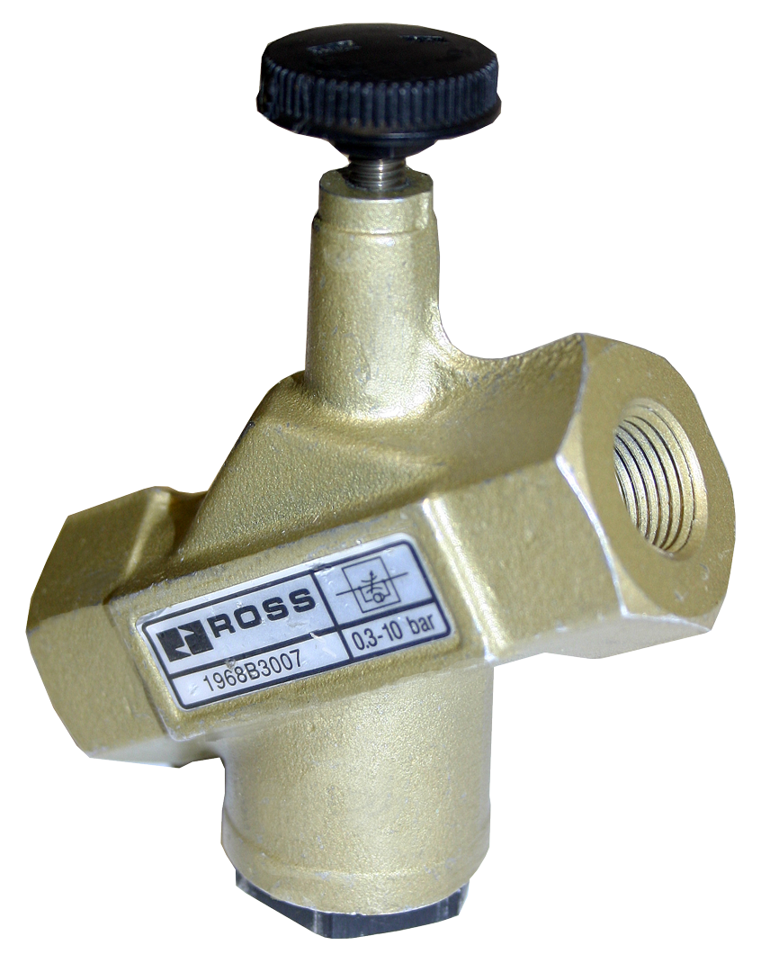
| 3/8" | 3/8 | 1968B3007 | 2.6 | 0.5 (0.2) |
| 1/2" | 3/8 | 1968B4017 | 2.6 | 0.5 (0.2) |
| 1/2" | 3/4 | 1968B4007 | 7.5 | 0.8 (0.4) |
| 3/4" | 3/4 | 1968B5007 | 8.3 | 0.8 (0.4) |
| 1" | 3/4 | 1968B6017 | 8.3 | 0.8 (0.4) |
| 1" | 1-1/4 | 1968B6007 | 17 | 2.2 (1.0) |
| 1-1/4" | 1-1/4 | 1968B7007 | 22 | 2.2 (1.0) |
| 1-1/2" | 1-1/4 | 1968B8017 | 22 | 2.2 (1.0) |
| 1-1/2" | 2 | 1968B8007 | 50 | 4.3 (1.9) |
| 2" | 2 | 1968B9007 | 50 | 4.3 (1.9) |
| 2-1/2" | 2 | 1968B9017 | 50 | 4.3 (1.9) |
Low-Profile High-Capacity Flow Control Valves
| port_size | body_size | model_npt | avg_cv | weight_lb_kg |
| 1/2" | 3/4 | 1968E4007 | 7.5 | 0.8 (0.4) |
| 3/4" | 3/4 | 1968E5007 | 8.3 | 0.8 (0.4) |
| 1" | 1-1/4 | 1968E6007 | 17 | 2.1 (1.0) |
| 1-1/4" | 1-1/4 | 1968E7007 | 22 | 2.1 (1.0) |
Right-Angle Flow Control Valves (11 Series) - Slot and Knob Adjustment - Tube fitting inlet models also available. Models with # have 1/8" threaded outlet with 1/4" inlet tube fitting.
| port_size | model_npt_slot | model_npt_knob | avg_cv | weight_lb_kg |
| 1/8" | 1968A1008 | 1968A1018 | 0.3 | 0.06-0.08 (0.03-0.04) |
| 1/4" | 1968A2008 | 1968A2018 | 0.6 | 0.12-0.14 (0.05-0.06) |
| 3/8" | 1968A3008 | 1968A3018 | 1.9 | 0.20 (0.09) |
| 1/2" | 1968A4008 | 1968A4018 | 2.8 | 0.34 (0.15) |
Related Products & Accessories
- Check Valves 19 Series (Series 262) - Self-actuating check valves with poppet construction for backflow prevention, low cracking pressure, and free flow in one direction. Available in low-profile, mid-range, and high-capacity versions. https://www.rosscontrols.com/en/series/262-check-valves
- Shuttle Valves 19 Series (Series 263) - Dual-inlet, single-outlet shuttle valves for OR-logic circuits allowing cylinder actuation from two independent control sources. https://www.rosscontrols.com/en/series/263-shuttle-valves
- Quick Exhaust Valves 18 Series (Series 264) - Poppet-construction quick exhaust valves that mount near the cylinder to dramatically reduce retraction cycle times by providing a short-path exhaust bypass. https://www.rosscontrols.com/en/series/264-quick-exhaust-valves
- Exhaust Silencers (Series 90) - Aluminum silencers rated to 290 psig for reducing exhaust noise at valve and cylinder exhaust ports. https://www.rosscontrols.com/en/series/90-silencers
- Lockout Valves L-O-X Series - OSHA-compliant lockout/tagout energy isolation valves for safe maintenance of pneumatic machinery. https://www.rosscontrols.com/en/series/1287-lockout-valves-15-series
Frequently Asked Questions (FAQ)
Q: What is the difference between the low-profile, high-capacity, and low-profile high-capacity series?
A: Low-profile models (1968F) are compact aluminum barstock valves for port sizes 1/8 through 1/2 in., optimized for space-constrained panels at Cv up to 2.3. High-capacity models (1968B) are cast aluminum valves for port sizes 1/4 through 2-1/2 in. with Cv up to 50, designed for large-bore cylinder control. Low-profile high-capacity models (1968E) are cast aluminum valves in 1/2 through 1-1/4 in. ports combining a compact body envelope with high-capacity Cv ratings up to 22, and add a visible brass stem indicator and positive locking mechanism.
Q: In which direction does the flow control restrict flow?
A: Flow control valves restrict flow in the meter-out direction, from port 2 (cylinder port) to port 1 (exhaust). In the supply direction (port 1 to port 2), the valve passes full flow unrestricted. This meter-out configuration controls cylinder retraction speed while allowing maximum flow during extension.
Q: What is the operating pressure range?
A: High-capacity, low-profile high-capacity, and right-angle models operate from 5 to 150 psig (0.3 to 10 bar). Low-profile models accept a supply pressure up to 217 psi (14.9 bar) with maximum operating pressure of 150 psi (10.3 bar).
Q: What temperature ranges are supported?
A: Low-profile models are rated for 41 to 140 F (5 to 60 C) ambient and media temperature, suitable for standard factory environments. High-capacity, low-profile high-capacity, and right-angle models support -40 to 175 F (-40 to 80 C), covering cold storage, outdoor, and elevated-temperature applications.
Q: How do I select between slot and knob adjustment?
A: Slot adjustment requires a standard flat-blade screwdriver, making it suitable for locked-down settings that resist inadvertent change. Knob adjustment is hand-operated for easy setup and tuning during commissioning without tools. In high-vibration environments, prefer slot or the locking mechanism on low-profile high-capacity models.
Q: How many turns does it take to go from fully closed to fully open?
A: The number of turns depends on port size. Low-profile models require 8 turns for 1/8 in. and 1/4 in. OT ports, and 10 turns for 1/4 through 1/2 in. ports. High-capacity and right-angle models require 14 turns for 1/4 and 3/8 in. ports, 12 turns for 1/2 and 3/4 in. ports, and 24 turns for 1 through 2-1/2 in. ports.
Q: How do I order BSPP (G thread) models?
A: Add a 'D' prefix to any standard NPT model number. For example, the 3/4 in. NPT high-capacity knob model is 1968B5007; the BSPP equivalent is D1968B5007. This applies to all families across the 19 Series and 11 Series right-angle valves.
Q: Can I mount the right-angle valve directly to a cylinder port?
A: Yes. The right-angle (11 Series) model is specifically designed for direct cylinder-port mounting. The inlet port swivels 360 degrees to allow optimal tubing routing to the supply source regardless of cylinder orientation, eliminating intermediate elbows or adapters.
Q: What filtration level is required?
A: A 5-micron filter is recommended for all 19 Series flow control valves. While the poppet design provides inherent dirt tolerance through self-cleaning action, particulate contamination will accelerate seal wear and degrade adjustment precision over time.
Q: Do the high-capacity valves have inline and offset port options?
A: Yes. The high-capacity series (1968B) is available in both inline orientation (ports on the same centerline) and offset orientation (ports on parallel but offset axes). Model numbers ending in 007 or 017 generally indicate inline and offset configurations respectively. Consult the ROSS catalog dimensional drawings to confirm offset dimensions for specific body sizes.
Q: What is the maximum Cv available in the 19 Series?
A: The maximum Cv is 50, achieved by the high-capacity models in 1-1/2 in., 2 in., and 2-1/2 in. port sizes with the 2 in. body size (models 1968B8007, 1968B9007, 1968B9017).
Q: Are tube fitting inlet options available?
A: Yes. The right-angle (11 Series) valve line includes models with tube fitting inlets in 1/8, 1/4, and 3/8 in. sizes (e.g., 1968A2108 for 1/4 in. tube fitting inlet with 1/8 in. NPT outlet). These enable direct tubing connection without separate fittings.
Q: What lubricant is compatible with these valves?
A: If lubrication is used in the air supply system, use only petroleum-base oils with oxidation inhibitors, an aniline point between 180 F (82 C) and 220 F (104 C), and ISO 32 or lighter viscosity. Avoid oils with phosphate-type additives, which can damage polyurethane components.
Q: Are 3D CAD models available?
A: CAD models are available for 19 Series flow control valve variants through the ROSS Controls website at rosscontrols.com. Contact ROSS Controls at (800) 438-7677 for assistance with specific model CAD availability.
Installation & Maintenance Guidelines
- Before installing or servicing any valve, shut down the complete pneumatic system, exhaust all pressure from the circuit, and lock out all energy sources per OSHA 1910.147 and EN 1037.
- Install a 5-micron air filter upstream of the flow control valve to prevent particulate contamination from degrading poppet sealing surfaces and adjustment needle performance.
- Orient flow control valves so that port 1 is the supply inlet from the control valve and port 2 is the cylinder port. The controlled (metered) flow direction is from port 2 toward port 1 during cylinder exhaust.
- Do not restrict the supply line upstream of the flow control valve. Undersized supply piping will reduce available pressure below the 5 psig minimum and can cause jerky, unpredictable cylinder motion independent of the flow control setting.
- For right-angle (11 Series) models, thread the valve directly into the cylinder port and swivel the inlet to the desired tubing orientation before tightening the inlet assembly. Do not overtighten, as excessive torque can crack the aluminum body.
- Apply thread sealant to male pipe threads only, not to female ports. Use PTFE tape or pipe thread compound compatible with compressed air service. Keep sealant away from the thread start to prevent contamination of the valve interior.
- Verify that supply pressure falls within the rated range (5 to 150 psig for high-capacity, low-profile high-capacity, and right-angle models; up to 217 psi for low-profile models). Operating below 5 psig minimum can result in incomplete valve response.
- For high-capacity and right-angle models installed in environments below 40 F (4 C), verify that compressed air supply is dried to a dew point below the minimum operating temperature to prevent ice formation inside the valve.
- After installation, set initial flow by turning the adjustment screw or knob fully clockwise (closed) and then turning counterclockwise (open) by the number of turns appropriate for the port size. Begin with approximately 50 percent of the full open range and adjust from there during system commissioning.
- On low-profile high-capacity models, engage the positive locking mechanism after completing flow adjustment to prevent inadvertent changes due to machine vibration. Verify the locking mechanism is released before attempting to readjust.
- Use only ROSS replacement parts and service kits when servicing 19 Series valves. Third-party seals or components may not meet the dimensional and material specifications required for correct poppet function and wear compensation.
- After installation and before returning the machine to service, perform a functional test by cycling the cylinder through the full stroke in both directions at the specified supply pressure and verifying that extension and retraction speeds match the design intent.
Warranty & Global Support
ROSS Controls provides a one-year warranty on all flow control valve products, covering defects in material and workmanship from date of purchase.
Global technical support is available through ROSS offices in the USA (headquarters in Ferndale, Michigan), Canada, Brazil, Germany, France, United Kingdom, India, China, and Japan.
Contact ROSS Controls USA Customer Service at 1-800-GET-ROSS (438-7677) or Technical Service at 1-888-TEK-ROSS (835-7677) for product selection, specification, and field troubleshooting assistance.
For complete dimensional drawings, flow coefficient data, and product configurator access, visit the ROSS Controls 19 Series product page at rosscontrols.com or download the Flow Control Valves catalog directly from the ROSS documents page.
Download Catalog: https://www.rosscontrols.com/en/documents/387
Download Documents
Flow Controls
