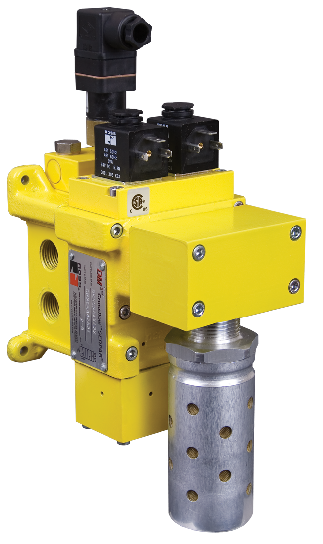
DM2C Series Double Valve Safety Category 4 PL e, Internal Monitoring, Manual Reset
- Redundant control can achieve Category 4, PL e, when used with proper safety controls
- Dynamic Monitoring, and air flow control functions are simply integrated into two identical valve elements
- Asynchronous movement of valve elements is detected by the dynamic monitoring and the valve latches in the safe condition, resulting in a residual outlet pressure of less than 1% of supply
- Manual valve reset
- Poppet design that is dirt tolerant, wear compensating for quick response and high flow capacity
- PTFE backup piston rings enhances valve endurance enabling operation with or without in-line lubrication
- Includes a pressure switch with both normally open (NO) and normally closed (NC) contacts to provide status feedback to the control system indicating whether the valve is in the lockout or ready-to-run condition
- High flow, clog resistant silencer included
- Base mounted for ease of valve replacement, captive valve-to-base mounting screws
- Inlet and outlet ports on both sides (plugs for unused ports included)
- SISTEMA Library available for download
loading...
loading...
Product Overview
The ROSS Controls DM2C Series (also referred to as DM2 Series C) is a redundant dual-poppet safe exhaust double valve that achieves Safety Category 4, Performance Level e (PL e) per ISO 13849-1:2015 and SIL 3 per IEC 62061. As a double valve with internal dynamic monitoring, the DM2C provides the highest achievable pneumatic safety category for applications where the risk assessment demands maximum risk reduction and where fault memory retention is required before machine restart.
The DM2C uses two identical valve elements operating in tandem. Internal dynamic monitoring continuously tracks the synchronized movement of both elements. If asynchronous movement is detected, the monitoring circuit detects the discrepancy and the valve latches in the safe condition, resulting in residual outlet pressure of less than 1 percent of supply pressure in the faulted state. This latching behavior is the fundamental design difference from the DM1 Series C: the DM2C retains its fault state even after supply pressure is removed and reapplied.
Reset from the faulted/latched condition is accomplished exclusively via the integrated electrical solenoid reset. The valve cannot be reset by simply removing and re-applying supply pressure. This deliberate design feature ensures that a qualified operator or maintenance technician must consciously issue a reset command to the valve after investigating and correcting the root cause of the fault, preventing inadvertent machine restart following a safety event.
Status feedback is provided by a mechanical pressure switch with both normally open (NO) and normally closed (NC) contacts. This switch reports whether the valve is in the locked-out condition or the ready-to-run condition. On select larger body configurations, the solenoid connection is provided via a 5-pin M12 connector. Power consumption for larger body valves is 15 watts. The DM2C family spans a wide range of body sizes, from compact Size 4 valves (3 Cv, 1/2 inch ports) through Size 30 units (20 Cv supply / 55 Cv exhaust, 1-1/2 inch inlet / 2 inch outlet / 2-1/2 inch exhaust), accommodating the largest pneumatic machine circuits.
The DM2C is base-mounted with captive valve-to-base screws, inlet and outlet ports on both sides, and an included high-flow clog-resistant silencer. SISTEMA Library files are available for download. Certifications include DGUV, CE, and EAC.
Key Engineering Features
- Safety Category 4, PL e (ISO 13849-1:2015) - Highest achievable pneumatic valve safety category when integrated with proper safety controls, satisfying maximum-risk-reduction requirements per ISO 12100 and ISO 13849.
- SIL 3 (IEC 62061) - Third-party certified SIL 3 safety integrity level for integration into the most demanding functional safety systems.
- Internal Dynamic Monitoring - Integrated monitoring continuously verifies synchronous movement of both valve elements. Asynchronous movement triggers immediate latching to the safe (exhausted) state with residual outlet pressure less than 1% of supply.
- Manual Solenoid Reset (Latching Fault Memory) - Fault state is latched and retained even after supply pressure removal. Reset requires a deliberate solenoid reset command, ensuring that a qualified person acknowledges and investigates the fault before machine restart is permitted.
- Cannot Reset by Pressure Removal - The valve design positively prevents reset by simply removing and re-applying supply pressure, eliminating the risk of inadvertent restart following a safety-critical valve fault.
- Mechanical Pressure Switch Feedback - Integrated mechanical pressure switch with NO and NC contacts reports locked-out or ready-to-run valve status to the machine control system.
- Wide Body Size Range (Size 4 to Size 30) - Sizes from 3 Cv (1/2" ports) through 20 Cv supply / 55 Cv exhaust (1-1/2" inlet, 2-1/2" exhaust) cover the full range of industrial pneumatic circuit flow requirements.
- Dual-Poppet Redundant Design - Two identical valve elements in tandem. A single element failure cannot prevent the safety function from executing, satisfying the Category 4 requirement for no dangerous failure from any single component fault.
- PTFE Backup Piston Rings - Enhances valve durability and enables reliable operation with or without in-line lubrication.
- Base Mount with Captive Screws - Valve body attaches to base with captive screws, allowing field valve replacement without disturbing piping. Ports on both sides for flexible circuit design.
- High-Flow Clog-Resistant Silencer Included - Factory-installed silencer on exhaust port. Clog-resistant design reduces exhaust noise while minimizing maintenance intervals.
- SISTEMA Library Support - Downloadable SISTEMA Library files for ISO 13849-1 Category 4, PL e documentation.
Technical Specifications
General Specifications
| Parameter | Specification |
| Safety Category | Category 4 |
| Performance Level | PL e per ISO 13849-1:2015 |
| Safety Integrity Level | SIL 3 per IEC 62061 |
| Monitoring Type | Internal dynamic monitoring |
| Reset Type | Manual via integrated solenoid; cannot reset by pressure removal/reapplication |
| Residual Outlet Pressure (fault condition) | Less than 1% of supply pressure |
| Valve Function | Redundant 3/2 single solenoid |
| Construction | Dual poppet |
| Actuation | Electrical (solenoid), 24 VDC |
| Feedback Type | Mechanical pressure switch, NO and NC contacts |
| Feedback Switch Rating | 0.1 A / 125-250 VAC; 0.1 A / 30 VDC; 0.3 A / 60 VDC |
| Feedback Connection | EN 175301-803 Form A |
| Power Consumption | 15 watts (standard); 5.8-6.5 watts (smaller sizes) |
| Solenoid Connection | EN 175301-803 Form A (standard); 5-pin M12 on select sizes |
| Voltage | 24 VDC |
| Operating Pressure Max | 120 psig (8.3 bar) |
| Pilot Supply | Internal |
| Thread Type | NPT and G (BSPP) |
| Mounting | Base mount |
| Ambient Temperature | 15 to 122 F (-10 to 50 C) |
| Media Temperature | 40 to 175 F (4 to 80 C) |
| Flow Media | Filtered, lubricated or unlubricated (mineral oils per DIN 51519, viscosity classes 32-46) |
| Valve Body Material | Cast aluminum |
| Poppet/Spool Material | Acetal and stainless steel |
| Seal Material | Buna-N |
| Piston Rings | PTFE backup |
| Silencer | High-flow, clog-resistant silencer included |
| Certifications | DGUV, CE, EAC |
Certifications & Compliance
| Certification/Standard | Detail |
| Safety Category / PL | Category 4, PL e per ISO 13849-1:2015 when integrated with proper safety controls. |
| Safety Integrity Level | SIL 3 per IEC 62061. |
| Residual Pressure (Fault State) | Less than 1% of supply pressure when latched in safe/fault condition. |
| DGUV Certification | DGUV certified for European industrial safety applications including press and forming machine requirements. |
| CE Marking | CE marked per EU Machinery Directive 2006/42/EC. |
| EAC Declaration | EAC declaration for Eurasian Economic Union markets. |
| SISTEMA Library | Downloadable SISTEMA Library files for ISO 13849-1 Category 4, PL e documentation. |
Typical Applications & Industries
Metal Forming, Stamping, and Press Operations
- High-tonnage mechanical and hydraulic power presses where the DM2C's fault-latching reset ensures that any detected valve discrepancy requires investigation and solenoid reset before the press is permitted to cycle, providing maximum audit traceability for press safety incidents.
- Multi-station progressive die and transfer press systems where the latching reset of the DM2C prevents operators from bypassing fault conditions by cycling power, ensuring root cause investigation is completed before restart.
- Forge press and die casting machine pneumatic controls where Category 4, SIL 3 is specified by corporate safety engineering standards, and where the manual solenoid reset requirement aligns with operator lock-out/restart procedures.
Automotive and Tier-1 Manufacturing
- Automotive body press and stamping operations where the DM2C's retained fault memory supports post-incident investigation by preserving the fault state until a maintenance engineer issues the solenoid reset.
- Powertrain assembly press operations with frequent worker access to the die area, where latching reset ensures no inadvertent restart after any pneumatic circuit anomaly.
- Automated welding and assembly cells with large-bore actuators requiring the highest exhaust flow rates available from the DM2C Size 30 (55 Cv exhaust) configuration.
Rubber, Plastics, and Composites Processing
- Rubber vulcanizing presses with high-pressure steam and pneumatic circuits where the DM2C's manual reset aligns with the plant's required step-by-step safety validation procedure before press re-closing.
- Large injection molding machines with Category 4 safe exhaust requirements for mold change operations, where the valve's latching capability prevents restart if the mold protection circuit detects any anomaly.
- Autoclave and composites curing systems with pneumatically controlled doors and clamps where fault latching ensures that a qualified technician authorizes any restart after an unexpected pressure event.
Material Handling and Heavy Industrial
- Large pneumatic conveyor divert gates, chute control, and bulk handling equipment where the high exhaust Cv of the DM2C Size 30 is required to rapidly depressurize large-volume circuits before personnel access.
- Pneumatically actuated industrial robots and cobot safety interfaces in Category 4 safety architectures requiring both redundancy and fault latching for comprehensive audit documentation.
- Steel service center pneumatic shear and press brake controls where the DM2C fulfills the Category 4 requirement specified in ANSI B11 machine tool standards.
Woodworking and Panel Products
- Multi-opening hot press systems for engineered wood products where the high-Cv DM2C can rapidly exhaust large-area pneumatic platen circuits and latch in the safe state if any platen pressure anomaly is detected.
- Edge banding and laminating press lines with pneumatic nip rolls and clamps requiring Category 4 energy isolation with documented fault history for quality and safety audit compliance.
General High-Risk OEM Applications
- Any OEM machine design where CE marking requires documented Category 4, PL e safe exhaust with fault latching, and the DM2C's DGUV certification and SISTEMA Library support the machine technical file.
- Facilities under ISO 45001 occupational safety management where the written energy control program specifies that any detected valve fault must be acknowledged by a solenoid reset before restart, which the DM2C design enforces at the hardware level.
Ordering and Model Number Configuration
The DM2C Series model number encodes valve configuration, thread type, body size, port sizes, voltage, and reset type. Example: DM2CNA66A21005 = DM2C Series, NPT thread, Basic Size 12, 1" inlet/outlet, 1-1/2" exhaust, 24 VDC. Contact ROSS Controls for the full configurator.
|
DM2C Series Model Number Structure:
DM2C Series designation (DM2C = Category 4 Double Valve, Internal Monitoring, Manual Reset)
N/D Thread type (N = NPT; D = G/BSPP)
A/B Revision/configuration code
Size Basic size code (e.g., 42 = Size 4 with 1/2" ports; 66 = Size 12 with 1" ports; 88 = Size 30)
A21 Voltage and electrical option code (24 VDC standard)
XXX Additional option codes |
Standard voltage: 24 VDC.
Solenoid connection: EN 175301-803 Form A standard; 5-pin M12 on select sizes.
Feedback switch connection: EN 175301-803 Form A.
NPT and G (BSPP) thread options available.
Multiple body sizes: contact ROSS for complete size matrix from Size 4 (1/2" ports, 3 Cv) through Size 30 (2" outlet, 55 Cv exhaust).
Operating pressure max: 120 psig (8.3 bar). Note: lower than DM1; verify against system design pressure.
Certifications: DGUV, CE, EAC. Specify required certification when ordering.
SISTEMA Library files downloadable at rosscontrols.com.
Contact ROSS Controls at (800) 438-7677 for full variant listing and application engineering support.
Accessories
Upstream FRL and Lockout L-O-X Assembly
ROSS MD Series FRL units and Lockout L-O-X valves for upstream air preparation and manual energy isolation, enabling complete Safe Air Entry System configurations with the DM2C safe exhaust valve.
Pressure Gauges and Transducers
Downstream pressure measurement accessories for visual and electronic monitoring of system pressure state, supplementing the mechanical pressure switch feedback for maintenance verification.
Mounting Brackets and Panel Hardware
Panel mounting brackets, port blocks, and end caps for enclosure integration and system layout flexibility.
Related Products & Accessories
- DM1 Series C Double Valve (Category 4, PL e, Auto Reset) - Same redundant dual-poppet architecture with automatic reset for applications where control system manages safety state transitions. https://www.rosscontrols.com/en/series/1294-dm1-series-c-double-valve
- DM2 Series C Explosion Proof (Category 4, PL e) - Explosion-proof variant of the DM2C for hazardous locations requiring solenoid reset and ATEX/NEC-rated coils. https://www.rosscontrols.com/en/series/1308-dm2-series-c-safe-exhaust-valve-explosion-proof
- M35 Series Double Valve (Category 4, PL e, External Monitoring) - Dual-poppet double valve with external PNP sensor monitoring for Category 4 applications. https://www.rosscontrols.com/en/series/1296-m35-series-double-valve
- RSe Series Double Valve (Category 4, PL e, External Monitoring) - Spool-type redundant double valve with PNP proximity sensors. https://www.rosscontrols.com/en/series/1297-rse-series-double-valve
- Safe Air Entry Assembly with DMC Series - Complete air entry system with Lockout L-O-X, FRL, and DM2C safe exhaust valve. https://www.rosscontrols.com/en/series/1286-safe-air-entry-assembly-with-dmc-series-safe-exhaust-valve
Frequently Asked Questions (FAQ)
Q: What is the key design difference between the DM2C and DM1 Series C?
A: Both valves achieve Category 4, PL e, SIL 3 with internal dynamic monitoring. The critical difference is reset behavior. The DM1 resets automatically when power is removed from both solenoids; if the abnormality has cleared, the valve is ready to run again. The DM2C latches in the faulted/safe state permanently until a deliberate solenoid reset command is issued. The DM2C design cannot be reset by removing and re-applying supply pressure, ensuring operator acknowledgment of the fault before restart.
Q: How is the DM2C reset after a fault?
A: Reset from the latched fault condition is performed exclusively by issuing an electrical signal to the integrated solenoid reset. This requires a deliberate command from the machine control system or a manual operator action, depending on the machine's safety control architecture. The reset command should only be issued after the fault has been investigated and the root cause corrected.
Q: What is the residual outlet pressure in the fault/latched condition?
A: When the internal monitoring detects asynchronous valve element movement and latches the valve, the residual outlet pressure is less than 1 percent of supply pressure. This near-complete pressure removal ensures the protected circuit is effectively de-energized in the fault state.
Q: What safety performance does the DM2C achieve?
A: Category 4, Performance Level e (PL e) per ISO 13849-1:2015 and SIL 3 per IEC 62061, identical to the DM1. The monitoring architecture (internal dynamic monitoring) also meets the same control reliability requirements. The distinction is exclusively in the reset behavior.
Q: What is the maximum flow capacity of the DM2C?
A: The DM2C is available from Size 4 (3 Cv supply, 6.5 Cv exhaust, 1/2" ports) through Size 30 (20 Cv supply, 55 Cv exhaust, 1-1/2" inlet / 2" outlet / 2-1/2" exhaust). The Size 30 is among the highest exhaust flow-capacity safe exhaust valves in the ROSS portfolio, suitable for large-bore cylinder circuits and high-volume zone exhaust applications.
Q: What is the maximum operating pressure?
A: 120 psig (8.3 bar). Note this is lower than the DM1 Series C's 150 psig (10.3 bar). Verify system design pressure against this limit when specifying the DM2C.
Q: What certifications does the DM2C carry?
A: DGUV certification, CE marking, and EAC declaration. SISTEMA Library files are available for ISO 13849-1 documentation.
Q: What is the feedback switch and what does it report?
A: A mechanical pressure switch with both NO and NC contacts reports two states: (1) ready-to-run, indicating normal valve operation with no fault detected; (2) locked out, indicating the valve has latched in the fault condition. The machine control must prevent a run signal while the locked-out state is indicated. The switch does not perform a physical lockout function.
Q: Can the DM2C be combined with a Lockout L-O-X valve?
A: Yes. For complete lockout/tagout compliance, pair the DM2C with an upstream Lockout L-O-X valve for manual padlockable energy isolation. ROSS offers complete Safe Air Entry Assembly configurations combining the DM2C, FRL units, and L-O-X lockout valves.
Q: How is the DM2C mounted?
A: The DM2C is base-mounted. The valve body attaches to the base with captive screws, and all field piping connects to the base. This allows valve body replacement without disturbing piping connections, reducing downtime. Inlet and outlet ports on both sides of the base provide flexible piping routing.
Q: Does the DM2C require lubrication?
A: No. PTFE backup piston rings enable reliable operation without in-line lubrication. If lubrication is used, specify a mineral oil per DIN 51519, viscosity class 32 to 46.
Q: Is a SISTEMA Library available?
A: Yes. A downloadable SISTEMA Library file for the DM2C Series is available at rosscontrols.com, containing the required safety parameters for ISO 13849-1 Category 4, PL e verification.
Installation & Maintenance Guidelines
- Mount the DM2C base assembly and connect all field piping before installing the valve body. All piping connects to base ports, not the valve body.
- Connect supply to one inlet port and plug the unused inlet. Connect the machine circuit to one outlet port and plug the unused outlet.
- Do not restrict the exhaust port or installed silencer. Replace silencer promptly if clogging is detected.
- Wire both operating solenoid connectors to the machine safety controller outputs. Both solenoids must be simultaneously de-energized to exhaust.
- Wire the solenoid reset connector to a separate controller output used exclusively for the reset function. The reset output must not be energized as part of normal machine operation.
- Wire the mechanical pressure switch (NO and NC) to the safety controller input. Program the controller to prevent machine restart if the locked-out state is detected.
- Program the control system to require a deliberate operator reset sequence: fault investigation, corrective action, then issue solenoid reset, then confirm ready-to-run feedback before permitting machine restart.
- Supply filtered compressed air. 5-micron filtration upstream recommended. Operating pressure: up to 120 psig (8.3 bar).
- Perform commissioning functional test including fault simulation to verify: (a) valve latches in safe state and feedback reports locked-out; (b) pressure cycling does not reset valve; (c) solenoid reset restores ready-to-run state.
- Document all commissioning results, fault simulation tests, and SISTEMA calculations in the machine technical file.
Warranty & Global Support
ROSS Controls provides a one-year warranty on all products, covering defects in material and workmanship from date of purchase.
Technical support: 1-888-TEK-ROSS (1-888-835-7677). Customer service: 1-800-GET-ROSS (1-800-438-7677).
Global support through ROSS offices in the USA (Ferndale, Michigan), Canada, Germany, France, United Kingdom, Brazil, India, China, and Japan.
SISTEMA Library files, dimensional drawings, CAD models, and certifications available at rosscontrols.com.
Download Catalog: https://www.rosscontrols.com/en/series/1295-dm2c-series-double-valve
Download Documents
DM2C Series Double Valve
